[Cristal] How to record sound on a microSD card with an ESP32 and a MAX9814 microphone ?
Introduction
Making sound recordings is undoubtedly an integral part of most electronic projects, which is why today I’m going to show you how to do this task in the simplest and most efficient way.
I advise you to get an ESP32, a MicroSD Card Module as well as a microSD card with the smallest capacity you have, in fact it will be useful to us only to store the audio file recorded (⚠️ IMPORTANT NOTE : the card must be formatted in FAT32 format), and a MAX9814 amplified electret microphone.
The ESP32 microcontroller has built-in analog-to-digital converters (ADCs) with a resolution of 12 bits, which allows for 4096 discrete levels of input. There are two ADCs on the ESP32, named ADC1 and ADC2. Each ADC has multiple channels:
- ADC1: 8 channels (GPIO 32 to GPIO 39)
- ADC2: 10 channels (GPIO 0, GPIO 2, GPIO 4, GPIO 12 to GPIO 15, GPIO 25 to GPIO 27)
In this article we will use ADC1 channel 7, that is GPIO35.
Sound is an analog signal, meaning it continuously varies in amplitude and frequency over time. The ADC in the ESP32 converts these continuous analog sound waves into digital data, which consists of discrete numerical values that can be processed by the microcontroller. The sampling rate determines the range of frequencies that can be accurately captured. According to the Nyquist theorem, the sampling rate should be at least twice the highest frequency you want to capture.
Wiring
Make the connections follow this:
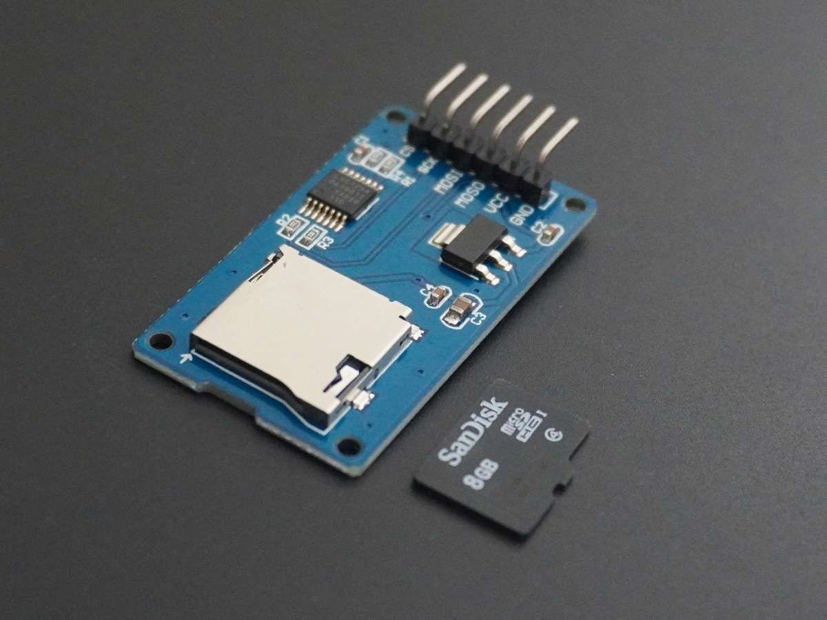
Micro SD Card Module :
- 3.3 V
- MISO : GPIO 19
- CLK : GPIO 18
- MOSI : GPIO 23
- CS : GPIO 5
- GND
![|inline]()
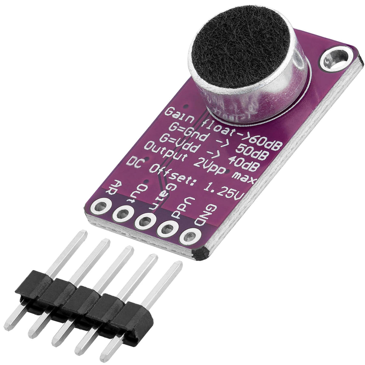
Microphone MAX9814 :
- VDD : 3.3 V
- OUT : GPIO 35 (ADC1_CHANNEL_7)
- GND
You may need pull-up resistors depending on your micro sd module…
Programming
We are going to record the audio in a WAV file, for this it is essential to define the headers inherent to this file format, here is an overview of the different characteristics to define in relation to our file to have a universally readable file :
[Master RIFF chunk]
   FileTypeBlocID  (4 bytes) : Identifier « RIFF »  (0x52, 0x49, 0x46, 0x46)
   FileSize        (4 bytes) : Overall file size minus 8 bytes
   FileFormatID    (4 bytes) : Format = « WAVE »  (0x57, 0x41, 0x56, 0x45)

[Chunk describing the data format]
   FormatBlocID    (4 bytes) : Identifier « fmt␣ »  (0x66, 0x6D, 0x74, 0x20)
   BlocSize        (4 bytes) : Chunk size minus 8 bytes, which is 16 bytes here  (0x10)
   AudioFormat     (2 bytes) : Audio format (1: PCM integer, 3: IEEE 754 float)
   NbrChannels     (2 bytes) : Number of channels
   Frequence       (4 bytes) : Sample rate (in hertz)
   BytePerSec      (4 bytes) : Number of bytes to read per second (Frequence * BytePerBloc).
   BytePerBloc     (2 bytes) : Number of bytes per block (NbrChannels * BitsPerSample / 8).
   BitsPerSample   (2 bytes) : Number of bits per sample

[Chunk containing the sampled data]
   DataBlocID      (4 bytes) : Identifier « data »  (0x64, 0x61, 0x74, 0x61)
   DataSize        (4 bytes) : SampledData size
   SampledData
Now let’s implement this in c++ in a wav-format file:
wav-format.h:
#include <Arduino.h>

// 16bit, monoral, 44100Hz,  linear PCM
void CreateWavHeader(byte* header, int waveDataSize);  // size of header is 44
wav-format.cpp:
#include "wav-format.h"

void CreateWavHeader(byte* header, int waveDataSize){
  header[0] = 'R';
  header[1] = 'I';
  header[2] = 'F';
  header[3] = 'F';
  unsigned int fileSizeMinus8 = waveDataSize + 44 - 8;
  header[4] = (byte)(fileSizeMinus8 & 0xFF);
  header[5] = (byte)((fileSizeMinus8 >> 8) & 0xFF);
  header[6] = (byte)((fileSizeMinus8 >> 16) & 0xFF);
  header[7] = (byte)((fileSizeMinus8 >> 24) & 0xFF);
  header[8] = 'W';
  header[9] = 'A';
  header[10] = 'V';
  header[11] = 'E';
  header[12] = 'f';
  header[13] = 'm';
  header[14] = 't';
  header[15] = ' ';
  header[16] = 0x10;  // linear PCM
  header[17] = 0x00;
  header[18] = 0x00;
  header[19] = 0x00;
  header[20] = 0x01;  // linear PCM
  header[21] = 0x00;
  header[22] = 0x01;  // monoral
  header[23] = 0x00;
  header[24] = 0x44;  // sampling rate 44100
  header[25] = 0xAC;
  header[26] = 0x00;
  header[27] = 0x00;
  header[28] = 0x88;  // Byte/sec = 44100x2x1 = 88200
  header[29] = 0x58;
  header[30] = 0x01;
  header[31] = 0x00;
  header[32] = 0x02;  // 16bit monoral
  header[33] = 0x00;
  header[34] = 0x10;  // 16bit
  header[35] = 0x00;
  header[36] = 'd';
  header[37] = 'a';
  header[38] = 't';
  header[39] = 'a';
  header[40] = (byte)(waveDataSize & 0xFF);
  header[41] = (byte)((waveDataSize >> 8) & 0xFF);
  header[42] = (byte)((waveDataSize >> 16) & 0xFF);
  header[43] = (byte)((waveDataSize >> 24) & 0xFF);
}
As you can see, we are using a sample rate of 44100Hz, but you can change this depending on your usage, just don’t forget to change the header values accordingly.
It is also necessary to properly configure the I2S protocol to perform the recording, so we will have the I2S file containing this very important configuration definition. Similarly, we will have the only two functions I2S_Read() and I2S_Write() useful to our main program.
I2S.h:
#include <Arduino.h>
#include "freertos/FreeRTOS.h"
#include "freertos/task.h"
#include "driver/i2s.h"
#include "esp_system.h"
#define SAMPLE_RATE (44100)
#define PIN_I2S_BCLK 26
#define PIN_I2S_LRC 22
#define PIN_I2S_DIN 34
#define PIN_I2S_DOUT 25

// This I2S specification :
//  -   LRC high is channel 2 (right).
//  -   LRC signal transitions once each word.
//  -   DATA is valid on the CLOCK rising edge.
//  -   Data bits are MSB first.
//  -   DATA bits are left-aligned with respect to LRC edge.
//  -   DATA bits are right-shifted by one with respect to LRC edges.
//        It's valid for ADMP441 (microphone) and MAX98357A (speaker).
//        It's not valid for SPH0645LM4H(microphone) and WM8960(microphon/speaker).
//
//  -   44100Hz
//  -   stereo

/// @parameter MODE : I2S_MODE_RX or I2S_MODE_TX
/// @parameter BPS : I2S_BITS_PER_SAMPLE_16BIT or I2S_BITS_PER_SAMPLE_32BIT
void I2S_Init(i2s_mode_t MODE, i2s_bits_per_sample_t BPS);

/// I2S_Read() for I2S_MODE_RX
/// @parameter data: pointer to buffer
/// @parameter numData: buffer size
/// @return Number of bytes read
int I2S_Read(char* data, int numData);

/// I2S_Write() for I2S_MODE_TX
/// @param data: pointer to buffer
/// @param numData: buffer size
void I2S_Write(char* data, int numData);I2S.cpp:
#include "I2S.h"

void I2S_Init(i2s_mode_t MODE, i2s_bits_per_sample_t BPS) {
    i2s_config_t i2s_config = {
        .mode = (i2s_mode_t)(I2S_MODE_MASTER | I2S_MODE_RX | I2S_MODE_TX | I2S_MODE_DAC_BUILT_IN | I2S_MODE_ADC_BUILT_IN),
        .sample_rate = SAMPLE_RATE,
        .bits_per_sample = BPS,
        .channel_format = I2S_CHANNEL_FMT_RIGHT_LEFT,
        .communication_format = (i2s_comm_format_t)(I2S_COMM_FORMAT_STAND_I2S),
        .intr_alloc_flags = 0,
        .dma_buf_count = 16,
        .dma_buf_len = 60
    };

    if (MODE == I2S_MODE_RX || MODE == I2S_MODE_TX) {
        Serial.println("using I2S_MODE");
        i2s_pin_config_t pin_config;
        pin_config.bck_io_num = PIN_I2S_BCLK;
        pin_config.ws_io_num = PIN_I2S_LRC;

        if (MODE == I2S_MODE_RX) {
            pin_config.data_out_num = I2S_PIN_NO_CHANGE;
            pin_config.data_in_num = PIN_I2S_DIN;
        } else if (MODE == I2S_MODE_TX) {
            pin_config.data_out_num = PIN_I2S_DOUT;
            pin_config.data_in_num = I2S_PIN_NO_CHANGE;
        }

        i2s_driver_install(I2S_NUM_0, &i2s_config, 0, NULL);
        i2s_set_pin(I2S_NUM_0, &pin_config);
        i2s_set_clk(I2S_NUM_0, SAMPLE_RATE, BPS, I2S_CHANNEL_STEREO);
    } else if (MODE == I2S_MODE_DAC_BUILT_IN || MODE == I2S_MODE_ADC_BUILT_IN) {
        Serial.println("Initialisation du protocole I2S...");
        i2s_driver_install(I2S_NUM_0, &i2s_config, 0, NULL);
        i2s_set_adc_mode(ADC_UNIT_1, ADC1_CHANNEL_7);  //GPIO35
    }
}

int I2S_Read(char *data, int numData) {
    size_t bytes_read = 0;
    i2s_read(I2S_NUM_0, (void *)data, numData, &bytes_read, portMAX_DELAY);
    return bytes_read;
}

void I2S_Write(char *data, int numData) {
    size_t bytes_written = 0;
    i2s_write(I2S_NUM_0, (const void *)data, numData, &bytes_written, portMAX_DELAY);
}
You will notice two separate definitions, one for an I2S protocol using an external ADC, and one using an internal ADC (I2S_MODE_ADC_BUILT_IN) which is our case! You can however use the first configuration if you are using a SoC that does not have an internal ADC.
Now it’s time to code the actual main audio recording program, we’ll call it rec-sound :
rec-sound.h:
#ifndef REC_H_
#define REC_H_

#include <SD.h>

void record_mic();

#endifrec-sound.cpp:
#include "Arduino.h"
#include <FS.h>
#include "wav-format.h"
#include "I2S.h"
#include <SD.h>

#define I2S_MODE I2S_MODE_ADC_BUILT_IN

const int record_time = 3;  // second
const char filename[] = "/audio.wav";

const int headerSize = 44;
const int waveDataSize = record_time * 88000;
const int numCommunicationData = 8000;
const int numPartWavData = numCommunicationData/4;
byte header[headerSize];
char communicationData[numCommunicationData];
char partWavData[numPartWavData];
File file;

bool driver_installed = false;

void record_mic() {

  if (!SD.begin()) Serial.println("SD begin failed");
  while(!SD.begin()){
    Serial.print(".");
    delay(500);
  }

  CreateWavHeader(header, waveDataSize);

  // Remove previous version of the record
  SD.remove(filename);

  file = SD.open(filename, FILE_WRITE);
  if (!file) return;

  file.write(header, headerSize);

  if (!driver_installed){
    I2S_Init(I2S_MODE, I2S_BITS_PER_SAMPLE_32BIT);
    driver_installed = true;
  }

  Serial.println("Démarrage de l'enregistrement...");
  for (int j = 0; j < waveDataSize/numPartWavData; ++j) {
    I2S_Read(communicationData, numCommunicationData);
    for (int i = 0; i < numCommunicationData/8; ++i) {
      partWavData[2*i] = communicationData[8*i + 2];
      partWavData[2*i + 1] = communicationData[8*i + 3];
    }
    file.write((const byte*)partWavData, numPartWavData);
  }

  file.close();
}
As you can see, we need the standard FS and SD libraries. You can also modify some constants according to your use such as the recording duration or the name of the recorded file, do not forget the “/” at the beginning of the file name as well as the “.wav” extension.
Now you just need to call the record_mic() function in your main code when you want to record a sound clip with the microphone, it can be activated with a button for example. Later if you want to transmit the recorded wav audio file to Linux server for any processing, do not hesitate to follow the tutorial I wrote here.
Auteur : Romain MELLAZA
Date de publication : 29 Juillet 2024